Friday, December 23, 2016

3D Printed Case

Ted Morin, lead developer of Plover, designed some cases to be 3D printed for a stenomod, and I have succeeded in doing that! Here's what it looks like. Find the design at  https://github.com/morinted/stenomod_case  if you'd like to try making your own.

Stenomod with 3D printed case
It took about 5 hours, and this is the first time the print wasn't ruined by having the tape lift around the edges. I'm not sure what the difference was, maybe temperature of the room? Anyway, I'm not sure I can rely on the process yet, so I'm not offering them for sale, not yet. Maybe when I feel more confident that I can repeat the process.


As I hope you can see I've put an extra rubber foot on the inside edge so they tent just a little bit. That's part of the point of the getting them off the wood deck, being be able to adjust their position more flexibly.

If you'd rather have 3D printed cases like this than the wooden deck I've been offering, let me know in the comments. I'll keep working on it.

Monday, December 19, 2016

Update

I know I said that I'd post some pictures of the process of making the wood decks, but I just haven't gotten around to it and I think it's time to admit that I'm not going to any time soon. So don't hold your breath waiting, please. Note to self to stop promising future postings.


Wednesday, November 23, 2016

Thanksgiving Holiday

This is just to say that for the next few days service will be a little slower than usual. Feel free to inquire but don't be surprised if it takes awhile for me to get back to you. Thanks!

Friday, October 14, 2016

Back to 8 bit

Quick update. I discovered that Adafruit doesn't support USB keyboard emulation on the M0 version of the Adalogger, so I ordered a couple of the 8 bit 32u4 feathers for more experiments. Not much point doing the translation in the micro if you can't get out it to the computer.

Wednesday, October 12, 2016

Side Trip, Adafruit Feather M0

First: You can still order a stenomod keyboard. Same price, same procedure. See the earlier post.

Now, I know I said I'd talk about making the wooden deck next, but I haven't needed to make one lately so I don't have any pictures yet. Instead I want to take a little side trip into some research I've been doing.

On Discord there's been some discussion about putting some version of Plover directly into a steno keyboard like the stenomod. For this and other reasons I'd like to see about using a more powerful processor in the next version of stenomod. I bought a couple copies of the Adafruit Feather M0 board, called the "Adalogger". It uses an ARM processor with 48k bytes RAM and 256 bytes flash. It also has an SD card socket on the board. Even if "Plover in the middle" doesn't work out, I'd like to use the SD card to record strokes without being attached to a computer the way some of the real steno keyboards do.

My first experiments with the new board involved getting an interpreter to run to make interactive testing go easier. I don't anticipate getting Forth going on this machine, so I want to make my C environment as comfortable as possible. I already had this interpreter working for the 8 bit AVR.

It turned out to be amazingly easy to port the interpreter to the M0! I used it to test pins and dump memory as I got to know something about this chip. I've committed the code to a github repository if anyone is interested, here. I have a newfound respect for the portability of the Arduino IDE.

As it stands you can test I/O pins, making them input, output, input_pullup, high, low, or get one to wiggle indefinitely. You can also do basic arithmetic and logic using a sort of a data stack to pass parameters. I say "sort of" because the data stack is circular like that in the Green Arrays F18A. There is no overflow nor underflow. One you're used to it it's a very powerful way to pass parameters. It's not hard to make new functions visible to the interpreter as you go.

Now that I've learned a little something about the Adalogger, I'm wiring up a prototype stenomod and adapting the stenomod-C code to work with it. I'll report back when I know more.

Tuesday, September 27, 2016

Making the cable

The last post showed me assembling a pair of stenomod PCBs. The right hand board needs to communicate with the Arduino on the left hand board, so they're connected by a 10 conductor ribbon cable. Here's how the cable is made.

Start with these parts. Some 10 conductor ribbon cable cut to a desired length and an IDC socket.


Insert the cable so that it barely pokes out the opposite end.


Put into a vice, like this.


And clamp it down tight, but not too tight. The connections are made automatically when the two parts of the IDC connector are clamped together.


Fold the cable over like this, before inserting the strain relief part.


Push the strain relief down so it snaps in, and you're done with one side.


Repeat on the other side and the cable has been made.


Note that the connectors need to have their keys facing the right way on each end in order to fit into the box on each PCB. It takes some visualization but isn't hard to figure out.


Next we'll look at making the wooden decks.

Monday, September 26, 2016

How a stenomod is assembled

Stenomod, a keyboard for amateur stenography, is for sale. See my last blog post for details.

It's time to start telling the story of the stenomod. I'm gonna do it out of order though. Before I tell how I got here, I want to show where "here" is. I want to show how a stenomod is assembled.


Here you see the two unstuffed printed circuit boards. The left hand board is on a wooden deck used as a template. Those round holes make space for the pins of the key switches to poke through.The first thing to do is to stuff all the switches.


Those aluminum legs make the PCB into a temporary soldering platform. As you'll see, the double length legs on one side allow space for the the diode leads to hang down before being soldered.

Here I'm soldering the switches in.


Next we stuff the box connectors into each board.


And hold them in place with a rubber band while soldering.


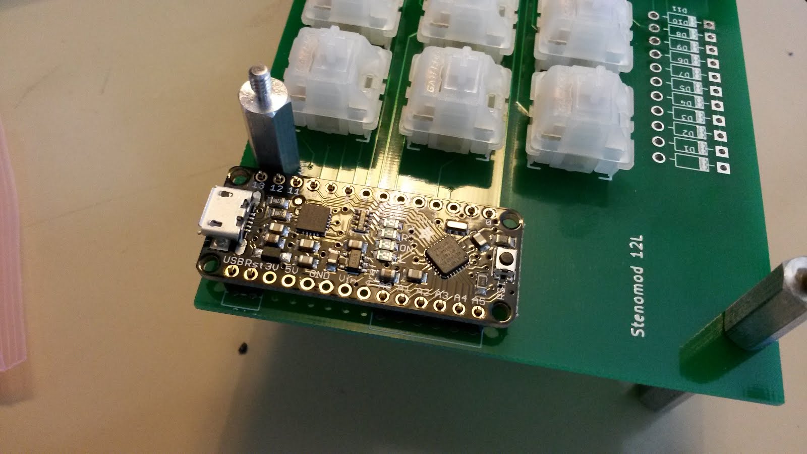
The left hand board needs to have the micro-controller soldered in. It's an Arduino Metro Mini, and comes with stake pins which we'll use to connect it to the stenomod board.


I cut the stake pins down to 2 and 6 pin pieces, insert them into the board and place the Arduino board onto them.


A rubber band holds the assembly together while soldering, both top and bottom.


The only things left to solder now are the diodes. Bend them with pliers and insert them, matching the black mark on the diode with the white mark on the board, to get the polarity right.


See how the leads dangle but don't touch the ground? I solder the diodes from the top to avoid having to secure them upside down.


Time to remove the temporary legs and snip off the leads.


The stake pins under the Arduino need to be snipped as well.


Now the finished boards can be put back in the template and the keycaps can be inserted.


That's it for the printed circuit boards.


Next time we'll make a cable to connect the two boards and a wooden deck to mount them on.